
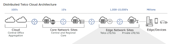
The deployment topology for 5G core and RAN architecture commonly used by Communication Service Providers (CSPs) can be realized by building the data center and network infrastructure based on hierarchical layers.
In this write up I’ll give a brief commentary about network interfaces required for proper communication.
As we have seen in earlier blog that the components are placed at different sites as per the design. The CU & DU components are also deployed & configured. The connectivity between RU, DU, CU & Core components happen on specific network interfaces. The network that connects RUs to DU’s is Fronthaul network. Midhaul refers to link between DU & CU, and Backhaul represents link between CU & the Core network.
Lets have a look at sample topology diagram
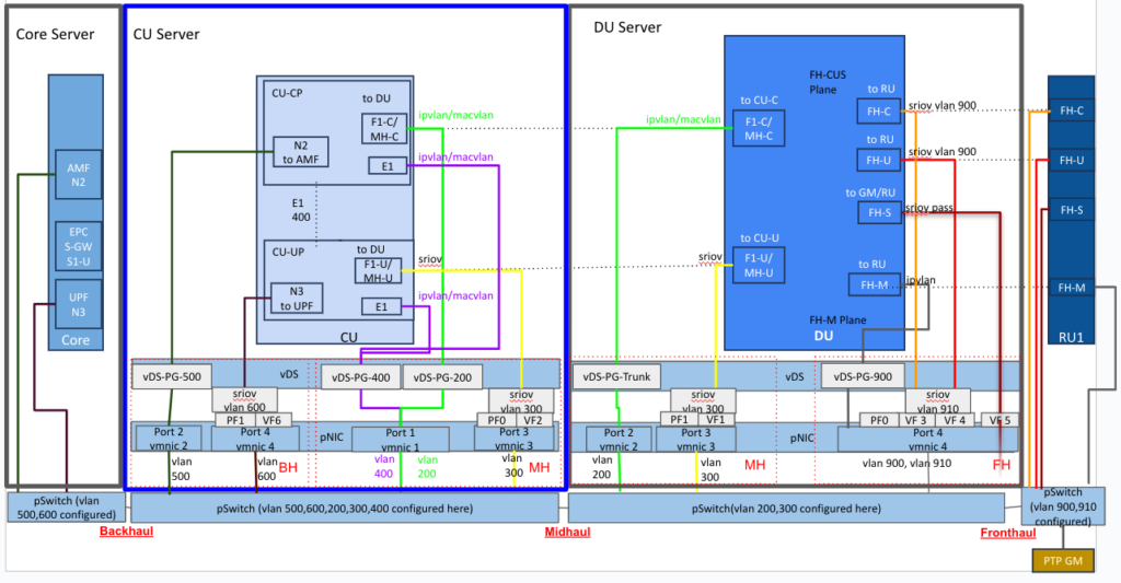
The different interfaces on which the workloads communicate can be seen. Lets have a look at them in the tabular format.
| Object | Interface | Interface Type | Connectivity purpose | Network Type |
| RU | FH-C | To DU’s FH-C (Control plane) | Fronthaul | |
| FH-U | To DU’s FH-U (User plane) | Fronthaul | ||
| FH-S | To DU’s FH-S (Synchronization plane) | Fronthaul | ||
| FH-M | To DU’s FH-M (Management plane) | Fronthaul | ||
| DU | FH-C | SRIOV | To RU’s FH-C (Control plane) | Fronthaul |
| FH-U | SRIOV | To RU’s FH-U (User plane) | Fronthaul | |
| FH-S | SRIOV Passthrough | To GM/RU’s FH-S (Synchronization plane) | Fronthaul | |
| FH-M | IPVLAN | To RU’s FH-M (Management plane) | Fronthaul | |
| F1-C Or MH-C | IPVLAN/MACVLAN | To CU-CP’s (Control Plane) F1-C Or MH-C | Midhaul | |
| F1-U Or MH-U | SRIOV | To CU-UP’s (User Plane) F1-U Or MH-U | Midhaul | |
| CU-CP | F1-C Or MH-C | IPVLAN/MACVLAN | To DU’s F1-C (Control Plane) | Midhaul |
| E1 | IPVLAN/MACVLAN | To CU-UP’s E1 | Internal between CU-CP & CU-UP | |
| N2 | To AMF | Backhaul | ||
| CU-UP | F1-U Or MH-U | SRIOV | To DU’s F1-U (User Plane) | Midhaul |
| E1 | IPVLAN/MACVLAN | To CU-CP’s E1 (Internal between CU-CP & CU-UP) | Internal between CU-CP & CU-UP | |
| N3 | To UPF | Backhaul |
Configuration of each interface will need a separate writeup. However in brief interfaces are created by making necessary changes at platform level (e.g. this blog Enable SRIOV in BIOS and vmnic ) and then creating it via CNF CSAR during deployment. TCA’s Late binding feature will then create these interfaces.
Hope this writeup gives you some idea about network interfaces for CNF’s.